Figure 1
A
Versatile Low Cost GPS Corrected Frequency Standard
(Updated on May 30, 2020)
A
frequency counter is present in many Amateur Radio Stations or
electronics workshops but, with the exception of the high-end models, its
accuracy and stability are generally in the 1-9 ppm range.
Some
counters have a connector for an accurate external time base,
generally 10 MHz. These time bases are expensive if purchased new and
scarce on the second-hand market.
I have such a frequency
counter in my ham shack and a frequency standard was needed to
improve its accuracy. The Global Positioning System (GPS) is one
solution to my problem.
There are mainly two ways of generating
a stable and accurate reference signal with the help of a GPS :
-
The PLL method makes use of the medium frequency signal (from 10 kHz
up to some MHz) provided with some GPS receivers. The PLL locks an
external 10 MHz time base to the GPS receiver. This is the best
method, but you need a GPS receiver with a medium frequency output.
-
Other methods are based on the 1 pulse per second (PPS) available in
almost all GPS, even the low-cost ones. The accuracy of this PPS
is generally better than 100 ns (often in the 10 to 30 ns range) and,
by averaging it over a long period, a much better accuracy can be
achieved.
Both methods have been described in many
articles and Web sites, thus I looked at them in order to select the
most appropriate to my needs. I was not looking for an uncertainty of
10-10 or better : a two-order improvement compared with
that of my frequency counter, i.e. a few parts per 10-8,
was my target.
1.
Description.
I selected the PPS method because
many low-cost GPS receivers found on eBay lack the medium frequency
output.
I was inspired by several articles :
- One published by G. Marcus W3PM in QEX July/August 2015 (1)
-
A 64-bit Si5351 Arduino library proposed by Jason Milldrum NT7S and
Dana H. Myers K6JQ (2).
- A Web page
presenting a program written by Igor Gonzales Martin : this program
shows how to read GPS information from the NMEA data streams
(3).
- And many others...
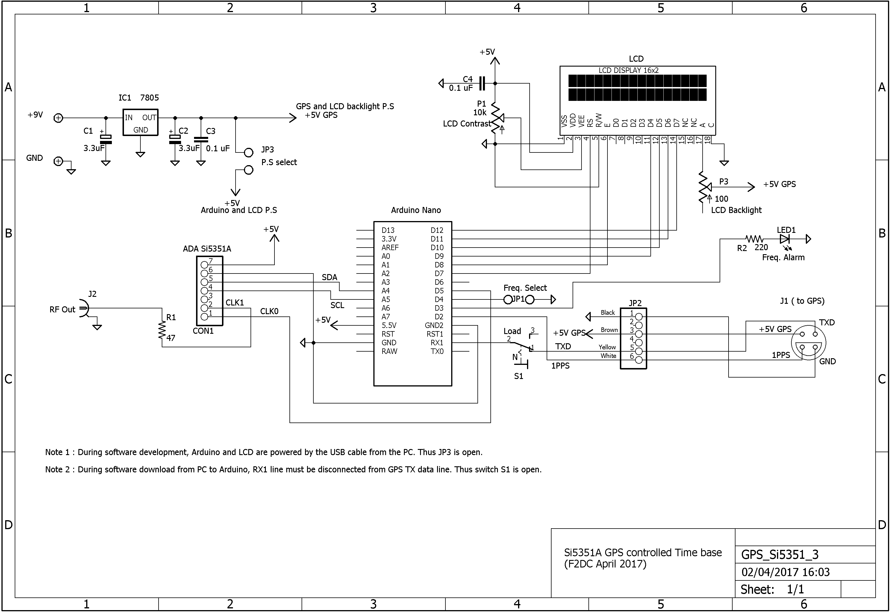
Figure
1 below shows the schematic diagram of my unit (click
here to enlarge) : an Adafruit Si5351 board generates the RF
signal and an Arduino Nano is doing almost all the work.
The
Si5351 is programed to deliver a 2.5 MHz signal on the CLK0 output
pin. This pin is connected to pin D5 of the Arduino which is the
input of its 16-bit internal counter. This counter measures the
number N of 2.5 MHz periods for 40 PPS cycles. If this frequency is
exactly 2.5 MHz, the counter register reads Ntrue=
2.5x106
x
40 = 108
pulses. If the 25 MHz Si5351 main clock differs from its nominal
frequency, then CLK0 will differ too and N will be lower or higher
than Ntrue.
The Arduino program will compute the new frequency calibration factor
and send it to the Si5351.
Because of the various errors (computation errors, 1 PPS jitter, method
of Si5351A frequency corrections, etc...) the overall accuracy of my
system is not better than +/- 1.5x10⁻⁸. Thus the Arduino software doesn't send any frequency correction to the Si5351A if the measured error E= N-Ntrue is lower than +/- 2x10⁻⁸.
The Si5351 second clock output CLK1
is the 10 MHz (or any other frequency) output.
The 25 MHz
crystal temperature drift was improved by attaching a small
heatsink to the crystal case, near the Si5351. You can see this
heatsink on the upper part of the Adafruit Si5351 board, in the
picture below.
During the first tests, I discovered that,
occasionally, strong RF signals near the unit could
disturb it. I added an alarm LED (connected to Arduino pin 3) on the
front panel to warn the user. An optional buzzer can be connected to
pin 3 to provide an audible alarm.
---------------------------------------------------------------------------------------------------------------------------------------
May 30, 2020 Updates
1/ New program version for use with the new NT7S Si5351 library
When
I wrote my Arduino sketch in 2016, the Jason Milldrum NT7S Si5351
available library was the 2.0.1 version. Later on, new revisions
were
published but the 'set_correction' function was different from
the older one : this function now needs two parameters instead of one.
Thus my old Arduino programs (up to V.4.1 included) can't be compiled
properly.
I modified my program recently so that it can be used with the new library and I tested it with the NT7S 2.1.4 revision. My new program is the
GPS_Si_ V5.2.
This new software code is available for download in the Download section.
The inside of the box, without the GPS
which is a few meters away, is presented on Figure 2A and the
rear panel on Figure 2B.
On
Fig. 2B we see the GPS connector on the left and the power supply 9V
jack. The switch 'N/LOAD' connects the Arduino RS232 input to the PC
during software development or to the GPS in normal mode


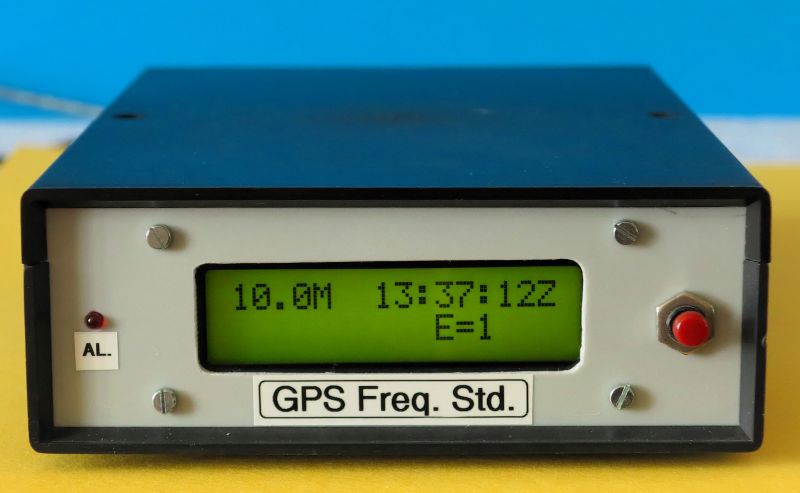
The
front panel is shown in Figure 3. The output frequency and GPS time
are displayed on the upper line of the LCD. The error E= N-
Ntrue (in parts per 10-8 ) is displayed on the right part of the second line :
the frequency error of the 10 MHz signal was E= 1x10⁻⁸ when
I took the picture.
The alarm LED is on the left and the red switch on the right is the Arduino Reset.

My
GPS receiver module is a UBLOX-NEO-6M coming with an antenna soldered
on the board. All the tests were conducted with the module inside my
ham shack, but near the ceiling to have a good view to the
satellites. The receiver is connected to the main unit by a 4 meters
shielded 4 conductor cable, the shield being soldered to the ground
at each end.
I put the GPS module in a plastic box to protect it
against dust and shocks (Figure 4). It is a clear plastic, so I can
see the blinking of the receiver LED from the outside and know that
the receiver is working properly.
2.
Testing the system.
I
wanted to test my system from
both the stability and accuracy points of view : it was long
and hard work and I modified the software many many times to
improve the behavior of my equipment.
2.1
Stability.
I don't have any high stability RF
generator to test my system and WWV reception is presently
not good in my area, especially for long-term testing. Some years ago
I was given a Pletronics 26 MHz OCXO : according to its technical
data, its aging accuracy is good enough (< 4 ppm accumulated for
10 years) and its frequency stability vs. temperature is better than
10-7 from -40°C to 85 °C. So I thought about the
simple test jig shown below (Figure 5) to evaluate my GPS frequency
standard.

The idea is to program the Si5351 frequency on 26.000800
MHz and to mix its signal with the 26.0000000 MHz from the OCXO. A
low-pass filter (Fc# 2.5 kHz) following the mixer rejects the RF and
keeps only the resulting 800 Hz. This audio frequency is sent to my
PC sound card for processing.
I used the Spectrum Lab software
from DL4YHF (4)
as
an FFT frequency estimator and to store the data in my PC hard disk.
J. Audet VE2AZX's paper (5) was a
big help for "setting me up" with Spectrum Lab.
The
schematic diagram of the mixer-low-pass filter unit is shown on
Figure 6.

Frequency measurements of the Pletronics OCXO showed
that its signal was around 26.000100 MHz. The beat frequency is thus
around 700 Hz (instead of 800 Hz) at the output of the mixer-low-pass
filter.
I
conducted many tests over the past few months to evaluate and improve the
performance of this system. Figure 7 presents a copy of
the Spectrum Lab screen during one of these tests. This
test was conducted from a cold start and one can see (lower part of
the picture) the large frequency jumps during the first 5 minutes.

Figure
7
After
these large jumps, the frequency corrections are around 0.8 Hz, i.e.
3x10⁻⁸ referenced to our 26 MHz signal. These small
frequency steps are linked to the resolution of the correction factor
which is +/- 10-8, as pointed out in the first part of
this paper.
Many long duration tests were also carried out and
Figure 8 shows one of them. It was obtained from a recorded Spectrum
Lab file and shows the full 5 hours experiment, the start of which is
presented on Figure 6 above.

2.2 Accuracy
measurement.
To estimate the
absolute accuracy I need to compare my signal to a high accuracy
reference signal. I looked at the short waves Web sites devoted to
frequency standard transmitters and found that RWM is a time and
frequency station in Russia, transmitting on 9.996 MHz. I can hear
this station on my receiver although its signal is not very strong
and is affected by fading (QSB). However it is the only short-wave
standard frequency transmitter I receive reasonably well !
I modified my
Arduino program to generate 9.995300 MHz, in order to get a 700 Hz
beat frequency at the audio output of my receiver. This audio
frequency is then sent to my PC audio card and processed by Spectrum
Lab which displays a spectrogram like the one shown on figure 9.

This picture is very different from figure 6 : the signal level is changing (QSB), the carrier is continous (CW) only for short time intervals and the S/N ratio is not as good. Anyway Spectrum Lab works wonders and extracts frequency information! One can see that the estimated frequency is 699.832 Hz instead of 700 Hz, i.e. around 2x10⁻⁸ absolute error at that time.
Conclusion.
This
is a simple frequency standard, costing less than $40, fulfilling my
needs and a very useful addition to my frequency counter.
Moreover,
it is a very versatile unit : generating any stable and accurate
frequency (up to 150 MHz or more) is just a matter of changing one
line of code.
Notes
(1)
G. Marcus W3PM,"An Arduino Controlled GPS Corrected VFO,"
QEX, July/August 2015, pp. 3-7
(2)
https://github.com/etherkit/Si5351Arduino
(3)
http://playground.arduino.cc/Tutorials/GPS
(4)
http://www.qsl.net/dl4yhf/spectra1.html
(5)
http://ve2azx.net/technical/FMT/SpecLabInfo.pdf