A RF sampler provides a low-power image of the RF signal propagating in a coaxial line. It is a 3 port device inserted between a power source (transmitter or amplifier) and the terminating load while its sample output (third port) is connected to a measuring equipment ( power meter, spectrum analyzer, oscilloscope, etc.).
Some characteristics of a typical sampler are summarized below :
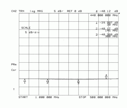
- It should have a known attenuation between its main ports and the sample port.
- Its attenuation plot should be as flat as possible over the usable frequency range.
- It should handle the power of the tested transmitter.
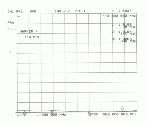
- Its Standing Wave Ratio (SWR) should be low over its frequency range.
There
are several methods to design such a sampler but one of
the simplest is a 50 ohms line associated with a resistive
divider. Years ago, W. Hayward, W7ZOI described such a device in
QST (1) : he used a brass stripline inside a Hammond 1590A
die cast box.
The reason for my design is that I wanted something easier to
duplicate, so I used a 50 ohms microstrip line etched on one side
of double-side Epoxy PCB instead of the Hayward's stripline.
1. The sampler.
The schematic appears on the left below and an inside view on the right.
The sampler is built on ordinary double-side Epoxy PCB so the 50 ohms microstrip is 2.8 mm wide : click here to download the PCB artwork (12 k PDF file).
R1, R2 and R3 values are computed in accordance with the required
coupling coefficient : I used R1=R2=R3= 820 ohms to get a
-40 dB coupling.
This resistor being rated at 0.25 W each, I can use my RF
sampler with transmitters up to 40 W continuous. If you want a
higher power limit (100 W) build this circuit with 3 x 820
ohms 0.5 W each.
The sampler is housed in a "tinplate Schubert
box" (37 x 55 x 30 mm).