A low Phase Noise +6 dBm (or more) Xtal Oscillator
(created April 25, 2012, updated May 31, 2025)
This oscillator circuit has a low phase noise and the elliptic low
pass filter found at its output helps to mitigate the harmonics. It was
inspired by ideas published by U. Rohde (1).
Its output power is +5.5 dBm and the harmonic 2 level is lower than -70 dBc.
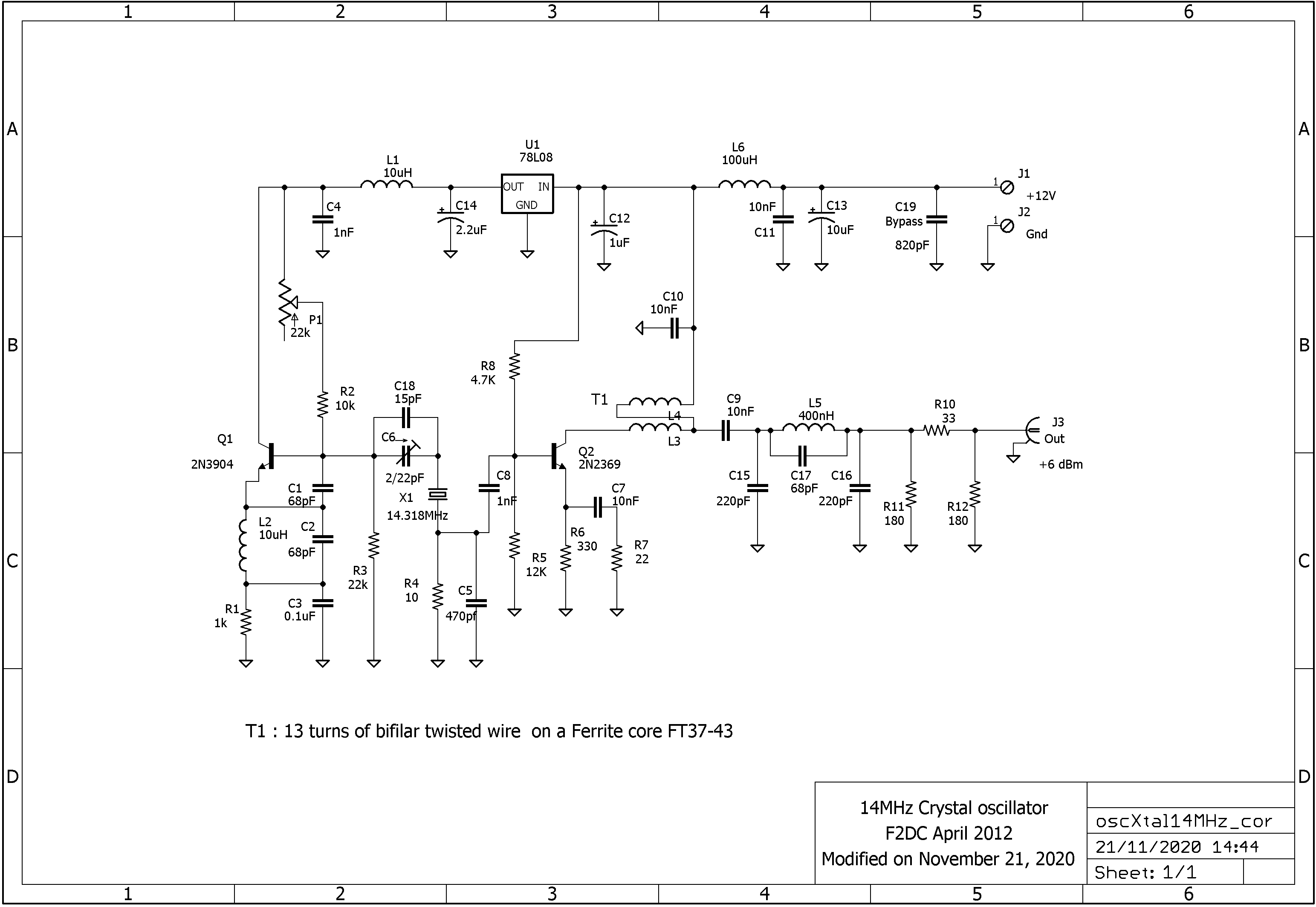
1. Schematic diagram.
It
is the low phase noise circuit published by U.L. Rhode but an amplifier
following the oscillator delivers more power and can be used when a
higher level is needed (as a Local Oscillator for a Double Balanced
Mixer for instance).
The output Pi attenuator is computed in
accordance with the output level you want (the one shown in the
schematic is around 5 dB).
Here is the schematic diagram (click on the picture to enlarge) :
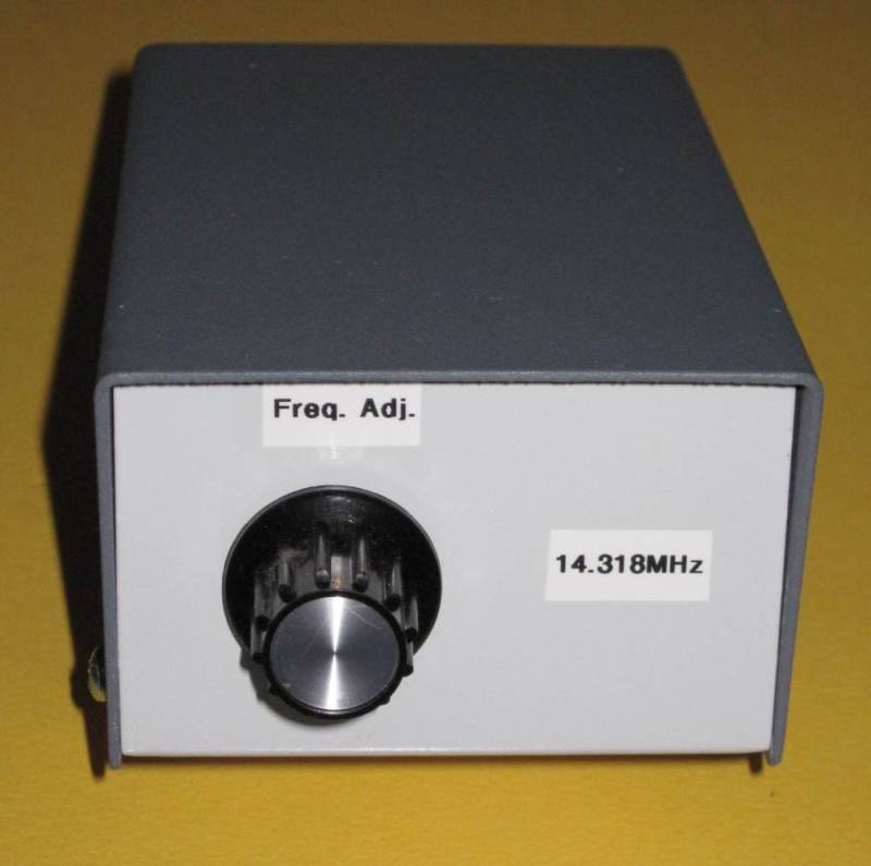
2. Construction.
This circuit is wired on an unetched PCB using the "Ugly method" popularized by Wes Hayward W7ZOI many years ago.
This is the oscillator housed in its aluminum case :
3. Results.
The
Peak to Peak voltage available at the output is around 1.20 Vp.p
when connected to an oscilloscope via a 50 Ohms load.
The
output power is about +5.5 dBm and the harmonic 2 level is lower than
-70 dBc (thus not visible on the spectrum below). If more power
(up to +10 dBm) is needed, you just have to modify the output
attenuator.
A HP141T spectrum analyzer generated this spectrum and the picture below is due to my SAN2PC interface presented in this Website
4. Variable frequency (VXO) type.
Sometimes
one needs a stable oscillator which frequency can be shifted a few kHz
from its nominal value (during Phase Noise measurements for instance).
In
order to conduct such tests, I have built a second oscillator identical
to the first, except that the adjustable capacitor C6 was replaced
by a variable one, controlled from the front panel.
This oscillator is shown below.
Note : the output level changes a few dB when frequency is moved
from its nominal value up to 5 kHz : take this level variation
into account, if necessary, when interpreting results.
(1) U.L. Rhode, Digital PLL Frequency Synthesizers Theory and Design, Prentice-Hall, Inc., Englewood Cliffs, 1983, pp. 197-200
Home